Index
- Eclipse IDE and JTAG
- Unlock STM32F103 with JTAG
- Flash firmware using Bluetooth
- Serial Port Bluetooth
- Serial Port Plot
- SM32F103C8T6 use 128kbytes flash
- Observer
- Shane Colton documentation and firmware
- Firmware
- Part 1: Field-Oriented
- Part 2: Field-Oriented
- Sensorless Pneu Scooter - part 1
- Sensorless Pneu Scooter - part 2
- Sensorless Pneu Scooter - part 3
- Texas Instruments videos
- Chinese controllers code
- Chinese balance group reference design
- Kerry D. Wong -- A Self-Balancing Robot
- Self balance bicycle
- PID
- LQR
- PID and LQR, MATLAB
- Steve Brunton videos
Part 2: Field-Oriented
Wednesday, January 13, 2010
3ph Duo Wrap-Up Part 2: Control
This is the conclusion to:
3ph Duo Wrap-Up Part 1: Field-Oriented
And falling squarely in the category of "ZOMG," the unabridged (but barely edited) 78-page Rev0 write-up that does not include specific software implementation at all yet because I am so sick of looking at it:
3ph Duo: 2 x 1kW Brushless Motor Controller
w/ Field Oriented Control
Design Notes [DRAFT]
It does have a lot of other cool stuff, though, including MOSFET selection and analysis, a more detailed F.O.C. explanation, BLDC vs. BLAC analysis, mechanical design, etc. etc. etc. I promise I will update it with some software details when I can stomach it again. Comments greatly appreciated...
When we left off, the controller was just barely able to generate six sine wave PWM outputs (three each for two motors) and estimate the position and speed of the rotor based on Hall effect sensors. Using this position estimate and current sensors, it could also measure the vector current, expressed in the two-dimensional d-q coordinate system we set up to make life easy. The purpose of Part 2 (of 2, thankfully) is to explain what we do with this information that makes field-oriented control so useful.
Part 1 hinted at the purpose of field-oriented control. (No, it's not just for making the motor quieter.) The goal is to place all of the current on the q-axis, right in between magnets, where it can pull hardest on the magnets and produce the most torque. Any current lagging behind onto the d-axis because of motor inductance is not doing useful work. This is now a controls problem.
I've taken just about every controls class at MIT (although I did drop a couple half-way through), so sometimes I take for granted that everyone understands the basics of a feedback control system. But for the sake of fulfilling my New Year's Resolution, I won't. The idea is really simple: You measure a value, in this case current, and compare it to the value you desire. If the desired value is higher than the measured value, you do something that will increase the current. If the desired value is lower than the measured value, you do something that will decrease the current. The result is a corrective action that always tries to bring the measured and desired values together. Textbook feedback loop:
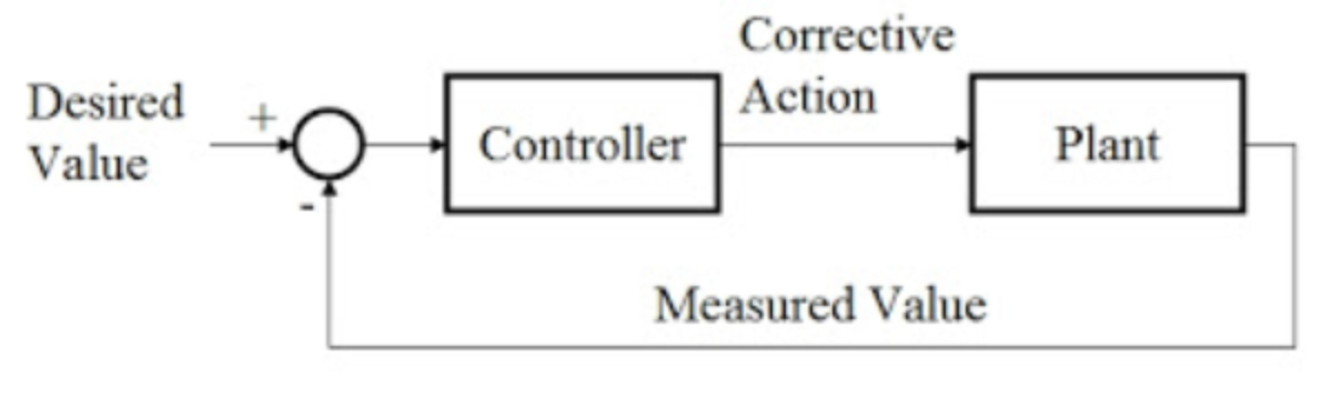
Not that kind of plant. Plant is whatever thing you are controlling.
It's borderline common sense. If the water's too hot, you turn the heat down. If it's too cold, you turn the heat up. If you're good, you can predict the overshoot and preemptively turn the heat down so as not to burn yourself. Eventually, you get to the right temperature. Only by adding math do we manage to make control systems more complicated than that.
Anyway, this is what we can do with both the d-axis and the q-axis current that we figured out how to measure in Part 1. Enter the "synchronous current regulator," a special application of the textbook feedback loop to these types of motor control problems. It's synchronous because it works in the rotating d-q coordinate system we set up before. A block diagram is worth 1,000 words in this case:
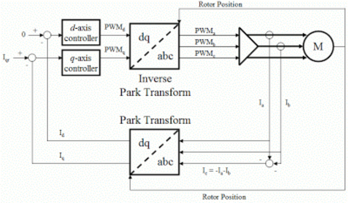
Synchronous Current Regulator. Click to enlarge.
Calm down, calm down, it's not that bad. The circle with the M? That's the motor. The triangle? That's the three-phase inverter, i.e. all of the power electronics hardware. Everything else is software. The Park transform? That's the trigonometry part that projects the A, B, and C coil current measurements onto the d-axis and q-axis, just like in Part 1. It needs the rotor position to do so. Then there are two feedback controllers: one for the d-axis and one for the q-axis. The d-axis controller's desired value is always zero. The q-axis controller's desired value is the torque command, and can be positive (accelerate) or negative (brake). The outputs, called PWMs, are switching signals that set the average voltage command on each of the three phases.
Now, that's not exactly what I did, but it's pretty damn close. Here's mine:
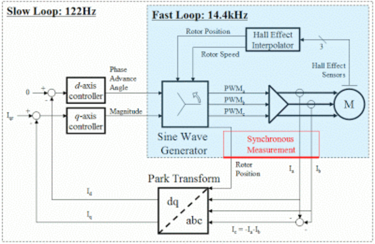
Modified Synchronous Current Regulator. Click to enlarge.
The differences are small. Instead of an inverse Park transform to project back from d-axis and q-axis voltage commands to A, B, and C voltage commands, I use the fast-loop sine wave generator that caused so much trouble in Part 1. And instead of a magical rotor position measurement, likely derived from an encoder or resolver, I use Hall effect sensors and interpolation. I chose to do this because cheap motors have Hall effect sensors, not encoders or resolvers.
The feedback loops are the same. Well...not quite. The difference is what comes out of the d-axis and q-axis controllers. Can you spot it? In the standard version, a d-axis and q-axis voltage (PWM) come out, then get tranformed back into values for A, B, and C voltage. This requires more trig in the fast loop...not good for my poor little processor. In the modified version, a phase (angle) and magnitude come out of the d-axis and q-axis controllers, respectively. Phase is a simple shift in the sine table...no big deal. Magnitude is a scaling operation, which, as we saw in Part 1 is still a pain in the ass on a microcontroller with no hardware multiplier, but it's not as bad as more trig. At least it scales all three values equally.
Where the heck did that modification come from? It's actually one of the first things I wrote down, and I never considered doing it anyway else. It's the least processor-intensive and most physically intuitive, IMO, even if it's non-standard. But does it actually work? Well, after about a month of screwing around with software, I finally got to the point where I could run this controller in earnest, under load, with the modified synchronous current regulator. First, here's what happens when the d-axis controller is turned off, meaning no phase angle correction can be implemented...the same as fixed-timing:
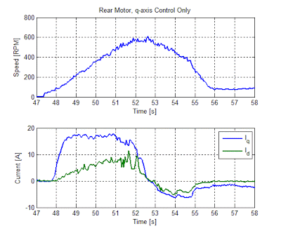
This looks very similar to the measurement done in Part 1 on the front motor. As the motor increases in speed, the effect of current lag is more and more pronounced, putting more current on the d-axis. The rear motor shows the effect even more, since it has a higher inductance. The controller tries to keep the q-axis, torque-producing current constant. The result is that the total current, the vector sum of d-axis and q-axis components (or of A, B, and C components), must increase in order to maintain constant torque.
Now the same motor and load with the d-axis phase control on,
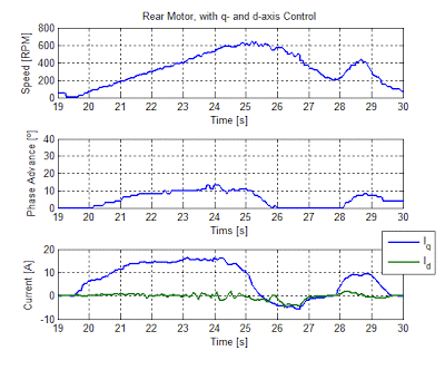
Plain as day, the phase advance takes out the d-axis current. Just 13º lead or so is all it takes on this motor at 600RPM. Meanwhile, the q-axis controller makes sure torque is held constant. If you want proof, look at the acceleration times in both cases...they are very similar. But in the case of full d- and q-axis control, the total current is reduced thanks to the zero d-axis component. This is clearly a more efficient operating point.
And just so you don't think I'm pulling your leg, it does work with two motors at the same time:
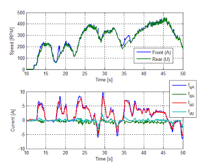
(Believe me, I did consider leaving this test out and hoping nobody would notice...)
Well there you have it, theorized and confirmed in experiment. The modified synchronous current regulator works. (I honestly was never sure it would, but I would have bet on it.) I can't compare it to the standard synchronous current regulator because the standard version simply would not run on my hardware. But, I did simulate the difference and I can assure you I was pleased with the result. If you don't believe me, read the unabridged version.
And that's the end of the 3ph Duo field-oriented control upgrade. What? Were you expecting some dramatic ending? That's not how things work when 90% of the upgrade is done in software. You do a lot of work for...something that looks the same as it did before. That's why there are no pictures of videos of real things in this post. The only good thing about code is that once you do it, you can copy-paste it for years. (Have you ever wondered where all my data comes from? I never talk about data acquisition software...)
Anyway, now that that's done, I feel the incredible urge to go build something. Something fast..... Posted by Shane Colton at 5:00 PM Labels: 3ph, BWD, motor control, scooter