Index
- Eclipse IDE and JTAG
- Unlock STM32F103 with JTAG
- Flash firmware using Bluetooth
- Serial Port Bluetooth
- Serial Port Plot
- SM32F103C8T6 use 128kbytes flash
- Observer
- Shane Colton documentation and firmware
- Firmware
- Part 1: Field-Oriented
- Part 2: Field-Oriented
- Sensorless Pneu Scooter - part 1
- Sensorless Pneu Scooter - part 2
- Sensorless Pneu Scooter - part 3
- Texas Instruments videos
- Chinese controllers code
- Chinese balance group reference design
- Kerry D. Wong -- A Self-Balancing Robot
- Self balance bicycle
- PID
- LQR
- PID and LQR, MATLAB
- Steve Brunton videos
DMA
http://letanphuc.net/2014/06/stm32-mpu6050-dma-i2c/
Using STM32 DMA and I2C to read data from MPU6050 – Updated
by Le Tan Phuc ⋅ 31 Comments In the previous post, an example of using STM32 DMA to perform a simple data copy between 2 arrays was introduced. Now, I will show another example with DMA and I2C to read raw data from MPU6050 acceleration and gyroscope sensor directly. Besides, a comparison to show timing difference between using and not using DMA is also mentioned.
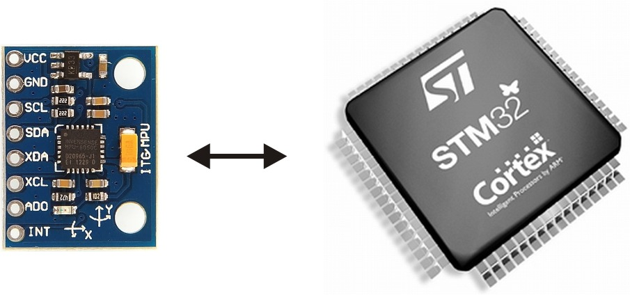 stm32 mpu6050
MPU6050 is a very popular MEMS acceleration and gyroscope sensor and other devices can connect and get data from it through I2C connection. There are a lot of libraries for Arduino that are available on the internet for connecting with MPU6050 and few libraries for STM32. Harinadha has done the porting job from MPU6050 Arduino library of Jeff Rowberg to STM32 here as well: http://harinadha.wordpress.com/2012/05/23/mpu6050lib/ without using INT pin (interrupt pin) of MPU6050. I also used this library at the first time and found it was quite difficult to get the most updated gyro data for calculation. So, I got the wrong gyro angle all the time. Moreover, I noticed that the code took lots of time to read 14 bytes of data (including 6 bytes acceleration, 2 bytes of temperature and 6 bytes of gyro), nearly 2ms, so there is no chance to get the sample rate at 1ms.
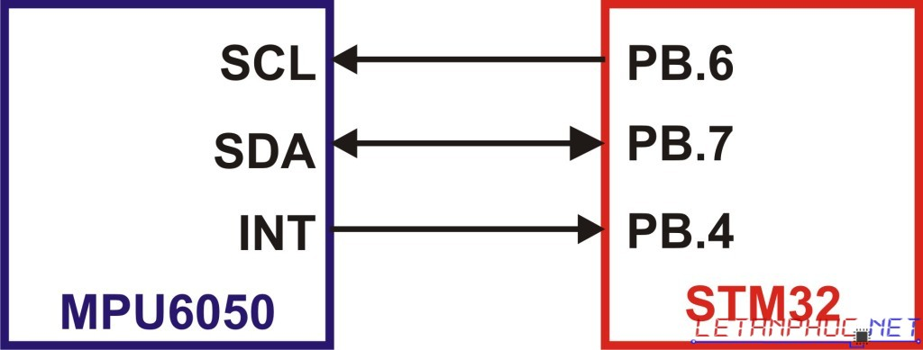 MPU6050 STM32 connection
Then I tried to look back at the code for Arduino and they actually used INT pin of MPU6050 to trigger the reading routine. So, I tried to edit the code of Harinadha to implement both INT triggering and DMA reading from I2C with some fine tune to give the best processing time. First, let’s have a look at the initialize routine for MPU6050. Again, Stdperiph driver V3.5.0 of ST was used here for basic I2C peripheral functions:
void MPU6050_Initialize(void) {MPU6050_Write(MPU6050_DEFAULT_ADDRESS, MPU6050_RA_PWR_MGMT_1, 1<<7);//reset the whole module firstdelay(50); //wait for 50ms for the gyro to stableMPU6050_Write(MPU6050_DEFAULT_ADDRESS, MPU6050_RA_PWR_MGMT_1, MPU6050_CLOCK_PLL_ZGYRO);//PLL with Z axis gyroscope reference MPU6050_Write(MPU6050_DEFAULT_ADDRESS, MPU6050_RA_CONFIG, 0x01); //DLPF_CFG = 1: Fs=1khz; bandwidth=42hz MPU6050_Write(MPU6050_DEFAULT_ADDRESS, MPU6050_RA_SMPLRT_DIV, 0x01); //500Hz sample rate ~ 2msMPU6050_Write(MPU6050_DEFAULT_ADDRESS, MPU6050_RA_GYRO_CONFIG, MPU6050_GYRO_FS_2000); //Gyro full scale settingMPU6050_Write(MPU6050_DEFAULT_ADDRESS, MPU6050_RA_ACCEL_CONFIG, MPU6050_ACCEL_FS_16); //Accel full scale settingMPU6050_Write(MPU6050_DEFAULT_ADDRESS, MPU6050_RA_INT_PIN_CFG, 1<<4); //interrupt status bits are cleared on any read operationMPU6050_Write(MPU6050_DEFAULT_ADDRESS, MPU6050_RA_INT_ENABLE, 1<<0); //interupt occurs when data is ready. The interupt routine is in the receiver.c file. MPU6050_Write(MPU6050_DEFAULT_ADDRESS, MPU6050_RA_SIGNAL_PATH_RESET, 0x07);//reset gyro and accel sensor}
| click me | click me |
|---|---|
| 12345678910111213141516171819202122 | void MPU6050_Initialize(void) {MPU6050_Write(MPU6050_DEFAULT_ADDRESS, MPU6050_RA_PWR_MGMT_1, 1<<7);//reset the whole module first delay(50);//wait for 50ms for the gyro to stable MPU6050_Write(MPU6050_DEFAULT_ADDRESS, MPU6050_RA_PWR_MGMT_1, MPU6050_CLOCK_PLL_ZGYRO);//PLL with Z axis gyroscope referenceMPU6050_Write(MPU6050_DEFAULT_ADDRESS, MPU6050_RA_CONFIG, 0x01);//DLPF_CFG = 1: Fs=1khz; bandwidth=42hz MPU6050_Write(MPU6050_DEFAULT_ADDRESS, MPU6050_RA_SMPLRT_DIV, 0x01);//500Hz sample rate ~ 2ms MPU6050_Write(MPU6050_DEFAULT_ADDRESS, MPU6050_RA_GYRO_CONFIG, MPU6050_GYRO_FS_2000);//Gyro full scale setting MPU6050_Write(MPU6050_DEFAULT_ADDRESS, MPU6050_RA_ACCEL_CONFIG, MPU6050_ACCEL_FS_16);//Accel full scale setting MPU6050_Write(MPU6050_DEFAULT_ADDRESS, MPU6050_RA_INT_PIN_CFG, 1<<4);//interrupt status bits are cleared on any read operation MPU6050_Write(MPU6050_DEFAULT_ADDRESS, MPU6050_RA_INT_ENABLE, 1<<0);//interupt occurs when data is ready. The interupt routine is in the receiver.c file. MPU6050_Write(MPU6050_DEFAULT_ADDRESS, MPU6050_RA_SIGNAL_PATH_RESET, 0x07);//reset gyro and accel sensor} |
With the MPU6050_Write function and I2C routine as follow:
void MPU6050_Write(uint8_t slaveAddr, uint8_t regAddr, uint8_t data) { uint8_t tmp; tmp = data; MPU6050_I2C_ByteWrite(slaveAddr,&tmp,regAddr); }//------------------------------------------------------------------void MPU6050_I2C_ByteWrite(u8 slaveAddr, u8* pBuffer, u8 writeAddr){/* Send START condition */I2C_GenerateSTART(MPU6050_I2C, ENABLE);/* Test on EV5 and clear it */while(!I2C_CheckEvent(MPU6050_I2C, I2C_EVENT_MASTER_MODE_SELECT));/* Send MPU6050 address for write */I2C_Send7bitAddress(MPU6050_I2C, slaveAddr, I2C_Direction_Transmitter);/* Test on EV6 and clear it */while(!I2C_CheckEvent(MPU6050_I2C, I2C_EVENT_MASTER_TRANSMITTER_MODE_SELECTED));/* Send the MPU6050's internal address to write to */I2C_SendData(MPU6050_I2C, writeAddr);/* Test on EV8 and clear it *///while(!I2C_CheckEvent(MPU6050_I2C, I2C_EVENT_MASTER_BYTE_TRANSMITTING));/* Send the byte to be written */if (pBuffer!=0) I2C_SendData(MPU6050_I2C, pBuffer);/* Test on EV8_2 and clear it */while(!I2C_CheckEvent(MPU6050_I2C, I2C_EVENT_MASTER_BYTE_TRANSMITTED));/* Send STOP condition */I2C_GenerateSTOP(MPU6050_I2C, ENABLE);}
| click me | click me |
|---|---|
| 123456789101112131415161718192021222324252627282930 | void MPU6050_Write(uint8_t slaveAddr, uint8_t regAddr, uint8_t data) { uint8_t tmp; tmp = data; MPU6050_I2C_ByteWrite(slaveAddr,&tmp,regAddr); }//------------------------------------------------------------------void MPU6050_I2C_ByteWrite(u8 slaveAddr, u8* pBuffer, u8 writeAddr){ /* Send START condition */I2C_GenerateSTART(MPU6050_I2C, ENABLE);/* Test on EV5 and clear it */while(!I2C_CheckEvent(MPU6050_I2C, I2C_EVENT_MASTER_MODE_SELECT));/* Send MPU6050 address for write */I2C_Send7bitAddress(MPU6050_I2C, slaveAddr, I2C_Direction_Transmitter);/* Test on EV6 and clear it */while(!I2C_CheckEvent(MPU6050_I2C, I2C_EVENT_MASTER_TRANSMITTER_MODE_SELECTED));/* Send the MPU6050's internal address to write to */I2C_SendData(MPU6050_I2C, writeAddr);/* Test on EV8 and clear it *///while(!I2C_CheckEvent(MPU6050_I2C, I2C_EVENT_MASTER_BYTE_TRANSMITTING));/* Send the byte to be written */if (pBuffer!=0) I2C_SendData(MPU6050_I2C, pBuffer);/* Test on EV8_2 and clear it */while(!I2C_CheckEvent(MPU6050_I2C, I2C_EVENT_MASTER_BYTE_TRANSMITTED));/* Send STOP condition */I2C_GenerateSTOP(MPU6050_I2C, ENABLE); } |
And those define registers of MPU6050 can be found here:
MPU6050.h
Here, we finish setting up the MPU6050 sensor. From now on, the sensor will run with the following configuration:
• Sample rate : 2ms
• Gyro full scale for X, Y and Z axis : +- 2000 degree/second. This means for example if the sensor is rotated in X axis with maximum angular velocity of 2000 degrees per second, the gyro X data will be maximum value of 16bit integer variable: 32768. In the other hand, the readout value will be -32768 if the angular velocity is -2000 degrees per second. From here, we can come out with the conversion ratio from raw sensor data to real angular velocity: r = 32768 / full scale value = 32768 / 2000 = 16.384.
• Accelerometer full scale: +- 16g.
• Fire interrupt signal when data is available. Clear interrupt flag whenever the data is completely read out.
Next, we need to configure DMA peripheral to connect with I2C as well:
NVIC_InitTypeDef NVIC_InitStructure;DMA_InitTypeDef DMA_InitStructure;DMA_DeInit(MPU6050_DMA_Channel); //reset DMA1 channe1 to default values;DMA_InitStructure.DMA_PeripheralBaseAddr = (uint32_t)I2C_DR_Address; //=0x40005410 : address of data reading register of I2C1DMA_InitStructure.DMA_MemoryBaseAddr = (uint32_t)I2C_Rx_Buffer; //variable to store dataDMA_InitStructure.DMA_M2M = DMA_M2M_Disable; //channel will be used for peripheral to memory transferDMA_InitStructure.DMA_Mode = DMA_Mode_Normal; //setting normal mode (non circular)DMA_InitStructure.DMA_Priority = DMA_Priority_Medium; //medium priorityDMA_InitStructure.DMA_DIR = DMA_DIR_PeripheralSRC; //Location assigned to peripheral register will be sourceDMA_InitStructure.DMA_BufferSize = 14; //number of data to be transferedDMA_InitStructure.DMA_PeripheralInc = DMA_PeripheralInc_Disable; //automatic memory increment disable for peripheralDMA_InitStructure.DMA_MemoryInc = DMA_MemoryInc_Enable; //automatic memory increment enable for memoryDMA_InitStructure.DMA_PeripheralDataSize = DMA_PeripheralDataSize_Byte; //source peripheral data size = 8bitDMA_InitStructure.DMA_MemoryDataSize = DMA_MemoryDataSize_Byte; //destination memory data size = 8bitDMA_Init(MPU6050_DMA_Channel, &DMA_InitStructure);DMA_ITConfig(MPU6050_DMA_Channel, DMA_IT_TC, ENABLE);NVIC_InitStructure.NVIC_IRQChannel = DMA1_Channel7_IRQn; //I2C1 connect to channel 7 of DMA1NVIC_InitStructure.NVIC_IRQChannelPreemptionPriority = 0x05;NVIC_InitStructure.NVIC_IRQChannelSubPriority = 0x05;NVIC_InitStructure.NVIC_IRQChannelCmd = ENABLE;NVIC_Init(&NVIC_InitStructure);
| click me | click me |
|---|---|
| 123456789101112131415161718192021222324 | NVIC_InitTypeDef NVIC_InitStructure;DMA_InitTypeDef DMA_InitStructure; DMA_DeInit(MPU6050_DMA_Channel); //reset DMA1 channe1 to default values; DMA_InitStructure.DMA_PeripheralBaseAddr = (uint32_t)I2C_DR_Address; //=0x40005410 : address of data reading register of I2C1DMA_InitStructure.DMA_MemoryBaseAddr = (uint32_t)I2C_Rx_Buffer; //variable to store dataDMA_InitStructure.DMA_M2M = DMA_M2M_Disable; //channel will be used for peripheral to memory transferDMA_InitStructure.DMA_Mode = DMA_Mode_Normal;//setting normal mode (non circular)DMA_InitStructure.DMA_Priority = DMA_Priority_Medium;//medium priorityDMA_InitStructure.DMA_DIR = DMA_DIR_PeripheralSRC;//Location assigned to peripheral register will be sourceDMA_InitStructure.DMA_BufferSize = 14;//number of data to be transferedDMA_InitStructure.DMA_PeripheralInc = DMA_PeripheralInc_Disable; //automatic memory increment disable for peripheralDMA_InitStructure.DMA_MemoryInc = DMA_MemoryInc_Enable;//automatic memory increment enable for memoryDMA_InitStructure.DMA_PeripheralDataSize = DMA_PeripheralDataSize_Byte;//source peripheral data size = 8bitDMA_InitStructure.DMA_MemoryDataSize = DMA_MemoryDataSize_Byte;//destination memory data size = 8bitDMA_Init(MPU6050_DMA_Channel, &DMA_InitStructure);DMA_ITConfig(MPU6050_DMA_Channel, DMA_IT_TC, ENABLE); NVIC_InitStructure.NVIC_IRQChannel = DMA1_Channel7_IRQn; //I2C1 connect to channel 7 of DMA1NVIC_InitStructure.NVIC_IRQChannelPreemptionPriority = 0x05;NVIC_InitStructure.NVIC_IRQChannelSubPriority = 0x05;NVIC_InitStructure.NVIC_IRQChannelCmd = ENABLE;NVIC_Init(&NVIC_InitStructure); |
The purpose of this configuration is to connect the I2C1 RX with the memory buffer directly using the corresponding DMA channel. We have some important points to notice here in order for you to be able to edit the code yourself in the future if you use a another I2C peripheral or different type of sensor with different byte to transfer through DMA:
• Which DMA to use ?
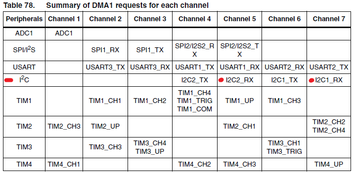
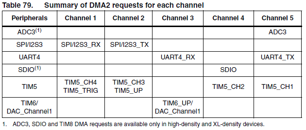
As you can see from the two tables from STM32F1 reference manual, there are 2 DMA blocks connected to different type of peripherals using different channels. Here we connect MPU6050 with I2C1 of STM32, so that the only choice is DMA1. Then, for reading data, we need to consider channel 7 that is connected to the RX register of I2C1 where all incoming data is stores. Later, if you want to use other peripherals with DMA in your own project, this table can be useful.
• What is the physical peripheral address:
Each peripheral inside the STM32 has a boundary address which can be found in Table 3 of the reference manual.
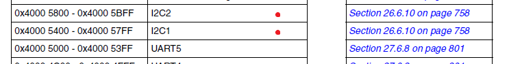
And inside that peripheral, there are several registers whose address are inside that peripheral boundary. For example, in our case, we need to locate the address of I2C_DR register (Data register) to assign to DMA controller.
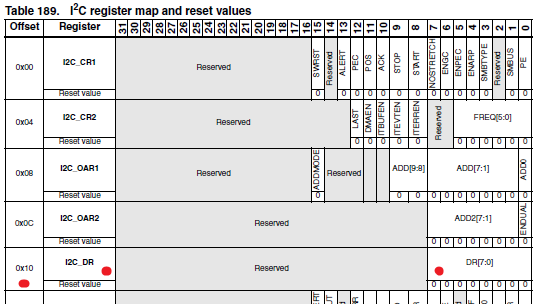
Notice the “Offset” column in Table 189, it means the physical address of I2C_DR register will be offset from the initial address of I2C1 (0x40005400) by 0x10 -> I2C_DR address is 0x40005410
• Number of byte to transfer:
As mentioned before, 14 bytes will be read from MPU6050, so DMA_Buffersize here should be 14 bytes.
After finishing the configuration parts, we move to the reading part. MPU6050 uses INT pin to trigger STM32 to read out its data as set before and we can use External Interrupt peripheral to capture it. The interrupt routine is as follow:
void EXTI4_IRQHandler(void){if (EXTI_GetITStatus(MPU6050_INT_Exti)) //MPU6050_INT{EXTI_ClearITPendingBit(MPU6050_INT_Exti);#ifndef USE_I2C_DMAPrepare_Gyro_Data(); //Read out the accel and gyro data whenever interrupt occurs.#elseI2C_DMA_Read(MPU6050_DEFAULT_ADDRESS, MPU6050_RA_ACCEL_XOUT_H,MPU6050);#endif}}
| click me | click me |
|---|---|
| 123456789101112 | void EXTI4_IRQHandler(void){if (EXTI_GetITStatus(MPU6050_INT_Exti))//MPU6050_INT{EXTI_ClearITPendingBit(MPU6050_INT_Exti);#ifndef USE_I2C_DMAPrepare_Gyro_Data();//Read out the accel and gyro data whenever interrupt occurs.#elseI2C_DMA_Read(MPU6050_DEFAULT_ADDRESS, MPU6050_RA_ACCEL_XOUT_H,MPU6050);#endif}} |
Noted the define “USE_I2C_DMA” I used to choose between regular way and DMA way of reading. Here the INT pin is connected to GPIO_Pin_4 of GPIOB so EXTI4 is activated. Then the I2C_DMA_Read function is presented:
void I2C_DMA_Read(u8 slaveAddr, u8 readAddr, u8 sensor){/* Disable DMA channel*/DMA_Cmd(MPU6050_DMA_Channel, DISABLE);/* Set current data number again to 14 for MPu6050, only possible after disabling the DMA channel */DMA_SetCurrDataCounter(MPU6050_DMA_Channel, 14);/* While the bus is busy */while(I2C_GetFlagStatus(MPU6050_I2C, I2C_FLAG_BUSY));/* Enable DMA NACK automatic generation */I2C_DMALastTransferCmd(MPU6050_I2C, ENABLE); //Note this one, very important/* Send START condition */I2C_GenerateSTART(MPU6050_I2C, ENABLE);/* Test on EV5 and clear it */while(!I2C_CheckEvent(MPU6050_I2C, I2C_EVENT_MASTER_MODE_SELECT));/* Send MPU6050 address for write */I2C_Send7bitAddress(MPU6050_I2C, slaveAddr, I2C_Direction_Transmitter); /* Test on EV6 and clear it */while(!I2C_CheckEvent(MPU6050_I2C, I2C_EVENT_MASTER_TRANSMITTER_MODE_SELECTED));/* Clear EV6 by setting again the PE bit */I2C_Cmd(MPU6050_I2C, ENABLE);/* Send the MPU6050's internal address to write to */I2C_SendData(MPU6050_I2C, readAddr);/* Test on EV8 and clear it */while(!I2C_CheckEvent(MPU6050_I2C, I2C_EVENT_MASTER_BYTE_TRANSMITTED));/* Send STRAT condition a second time */I2C_GenerateSTART(MPU6050_I2C, ENABLE);/* Test on EV5 and clear it */while(!I2C_CheckEvent(MPU6050_I2C, I2C_EVENT_MASTER_MODE_SELECT));/* Send MPU6050 address for read */I2C_Send7bitAddress(MPU6050_I2C, slaveAddr, I2C_Direction_Receiver);/* Test on EV6 and clear it */while(!I2C_CheckEvent(MPU6050_I2C, I2C_EVENT_MASTER_RECEIVER_MODE_SELECTED));/* Start DMA to receive data from I2C */DMA_Cmd(MPU6050_DMA_Channel, ENABLE);I2C_DMACmd(MPU6050_I2C, ENABLE);// When the data transmission is complete, it will automatically jump to DMA interrupt routine to finish the rest.//now go back to the main routine}
| click me | click me |
|---|---|
| 1234567891011121314151617181920212223242526272829303132333435363738394041424344454647484950515253 | void I2C_DMA_Read(u8 slaveAddr, u8 readAddr, u8 sensor){/* Disable DMA channel*/DMA_Cmd(MPU6050_DMA_Channel, DISABLE);/* Set current data number again to 14 for MPu6050, only possible after disabling the DMA channel */DMA_SetCurrDataCounter(MPU6050_DMA_Channel, 14); /* While the bus is busy */while(I2C_GetFlagStatus(MPU6050_I2C, I2C_FLAG_BUSY)); /* Enable DMA NACK automatic generation */I2C_DMALastTransferCmd(MPU6050_I2C, ENABLE);//Note this one, very important /* Send START condition */I2C_GenerateSTART(MPU6050_I2C, ENABLE); /* Test on EV5 and clear it */while(!I2C_CheckEvent(MPU6050_I2C, I2C_EVENT_MASTER_MODE_SELECT)); /* Send MPU6050 address for write */I2C_Send7bitAddress(MPU6050_I2C, slaveAddr, I2C_Direction_Transmitter); /* Test on EV6 and clear it */while(!I2C_CheckEvent(MPU6050_I2C, I2C_EVENT_MASTER_TRANSMITTER_MODE_SELECTED)); /* Clear EV6 by setting again the PE bit */I2C_Cmd(MPU6050_I2C, ENABLE); /* Send the MPU6050's internal address to write to */I2C_SendData(MPU6050_I2C, readAddr); /* Test on EV8 and clear it */while(!I2C_CheckEvent(MPU6050_I2C, I2C_EVENT_MASTER_BYTE_TRANSMITTED)); /* Send STRAT condition a second time */I2C_GenerateSTART(MPU6050_I2C, ENABLE); /* Test on EV5 and clear it */while(!I2C_CheckEvent(MPU6050_I2C, I2C_EVENT_MASTER_MODE_SELECT)); /* Send MPU6050 address for read */I2C_Send7bitAddress(MPU6050_I2C, slaveAddr, I2C_Direction_Receiver); /* Test on EV6 and clear it */while(!I2C_CheckEvent(MPU6050_I2C, I2C_EVENT_MASTER_RECEIVER_MODE_SELECTED)); /* Start DMA to receive data from I2C */DMA_Cmd(MPU6050_DMA_Channel, ENABLE);I2C_DMACmd(MPU6050_I2C, ENABLE); // When the data transmission is complete, it will automatically jump to DMA interrupt routine to finish the rest.//now go back to the main routine} |
And DMA interrupt routine:
void DMA1_Channel7_IRQHandler(void){if (DMA_GetFlagStatus(DMA1_FLAG_TC7)){/* Clear transmission complete flag */DMA_ClearFlag(DMA1_FLAG_TC7);I2C_DMACmd(MPU6050_I2C, DISABLE);/* Send I2C1 STOP Condition */I2C_GenerateSTOP(MPU6050_I2C, ENABLE);/* Disable DMA channel*/DMA_Cmd(MPU6050_DMA_Channel, DISABLE);//Read Accel data from byte 0 to byte 2for(i=0; i<3; i++) AccelGyro[i]=((s16)((u16)I2C_Rx_Buffer[2*i] << 8) + I2C_Rx_Buffer[2*i+1]);//Skip byte 3 of temperature data//Read Gyro data from byte 4 to byte 6for(i=4; i<7; i++)AccelGyro[i-1]=((s16)((u16)I2C_Rx_Buffer[2*i] << 8) + I2C_Rx_Buffer[2*i+1]); }}
| click me | click me |
|---|---|
| 1234567891011121314151617181920212223 | void DMA1_Channel7_IRQHandler(void){if (DMA_GetFlagStatus(DMA1_FLAG_TC7)){/* Clear transmission complete flag */DMA_ClearFlag(DMA1_FLAG_TC7); I2C_DMACmd(MPU6050_I2C, DISABLE);/* Send I2C1 STOP Condition */I2C_GenerateSTOP(MPU6050_I2C, ENABLE);/* Disable DMA channel*/DMA_Cmd(MPU6050_DMA_Channel, DISABLE); //Read Accel data from byte 0 to byte 2for(i=0; i<3; i++) AccelGyro[i]=((s16)((u16)I2C_Rx_Buffer[2*i] << 8) + I2C_Rx_Buffer[2*i+1]);//Skip byte 3 of temperature data//Read Gyro data from byte 4 to byte 6for(i=4; i<7; i++)AccelGyro[i-1]=((s16)((u16)I2C_Rx_Buffer[2*i] << 8) + I2C_Rx_Buffer[2*i+1]);}} |
Now, the reading sequence will be done automatically and store into AccelGyro variable with the minimum time needed. I have also done a timing test to check how efficient this method could be. Following figures show the timing consume of two method: regular reading and DMA reading.
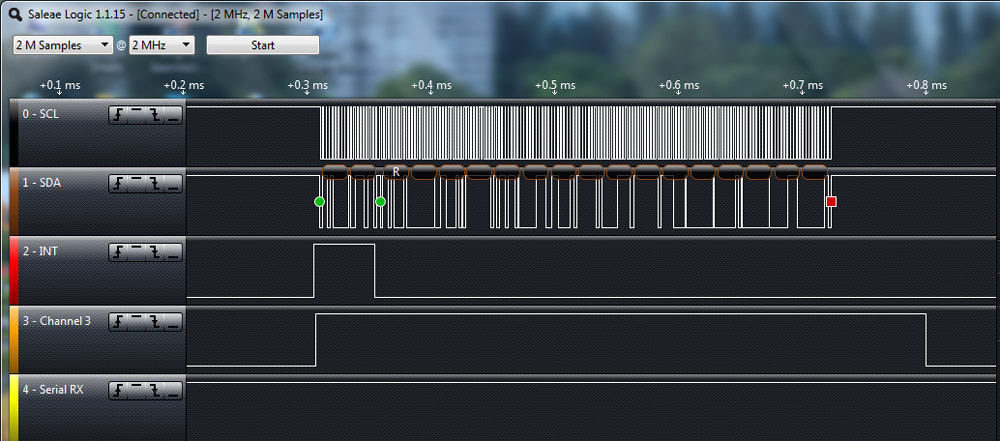
Fig: regular I2C reading
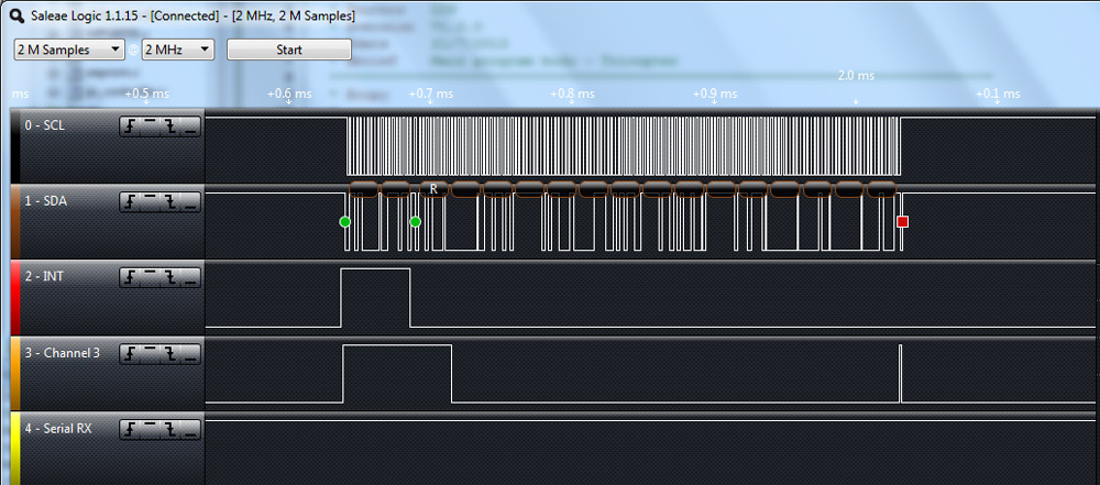
Fig: DMA supported reading
Channel 3 in both figures shows the timing period when CPU is dealing with I2C reading. With the normal way of reading I2C data, CPU is busy for the whole period and cannot do anything else. This could lead to delay in reading other sensor data as well. By using DMA, we can free the CPU to do other task as DMA handles all the reading part from I2C peripheral.
Hope you can find this article useful and let’s wait for more to come
