Index
- Eclipse IDE and JTAG
- Unlock STM32F103 with JTAG
- Flash firmware using Bluetooth
- Serial Port Bluetooth
- Serial Port Plot
- SM32F103C8T6 use 128kbytes flash
- Observer
- Shane Colton documentation and firmware
- Firmware
- Part 1: Field-Oriented
- Part 2: Field-Oriented
- Sensorless Pneu Scooter - part 1
- Sensorless Pneu Scooter - part 2
- Sensorless Pneu Scooter - part 3
- Texas Instruments videos
- Chinese controllers code
- Chinese balance group reference design
- Kerry D. Wong -- A Self-Balancing Robot
- Self balance bicycle
- PID
- LQR
- PID and LQR, MATLAB
- Steve Brunton videos
Hall effect sensor placement
http://mitrocketscience.blogspot.pt/2011/08/hall-effect-sensor-placement-for.htmlHall Effect Sensor Placement for Permanent Magnet Brushless DC Motors
This is a very confusing topic.
I spent a few hours today re-teaching myself the theory for hall effect sensor locations, then even longer trying to come up with a clear way to present it. It was a combination of gathering information from forums and looking back at my old notes (which were derived from Shane's expertise). The goal of this post is to gather all of that information on one webpage and relay it in as clear a format as I can.
Disclaimer: I am not an electrical engineer, so some of this may not be accurate. That being said, I'm 90% confident that it is.
Legend:
• edeg : electrical degrees
• erot: electrical rotation. 1 erot = 360 edeg
• mdeg : mechanical degrees
• mrot: mechanical rotation. 1 mrot = 360 mdeg
• pp : number of magnet pole pairs . 1 pp = 2 magnets (1 north, 1 south)
• s : number of slots (in the stator)
This post will cover how to place hall effect sensors onto 3 phase motors being run by 60 edeg and 120 edeg hall position controllers (motor controllers that expect the hall sensors to be placed 60 and/or 120 edeg apart). While it is feasible to design a motor controller to expect the hall sensors to placed some other number of edeg apart, I have never seen or heard of one (there just aren't any common commercially available ones that accept anything other than 60 and/or 120 edeg hall sensor placement). I believe the reason for this is that it makes the code and following math more complicated, though I could be wrong as I have never designed my own motor controller. I'm only going to cover 3 phase motors in this post because they are the most common type, though the following equations could be extended to any number-of-phase motors with minor modifications.
We need to figure out where to place the 3 hall effect sensors. Let's start with some math:
The first thing you want to find is the number of mdeg per erot . In other words, the number of mechanical degrees the rotor spins to make one complete electrical rotation.
Equation 1: (360 mdeg / pp) = n mdeg per erot =n mdeg per 360 edeg
Note: don't confuse this with the equation mrpm * pp = erpm, which is useful for finding electrical rpm given the mechanical rpm of your motor.
Now, let's say you want to use a motor controller that requires 120 edeg hall effect sensor placement. You need to find the number of mdeg per 120 edeg. So you just divide the above equation by 3.
Equation 2: (360 mdeg / 3*pp) = m mdeg per 120 edeg.
This value, m, gives the minimum number of mdeg that you can space each of the hall effect sensors apart and still achieve 120 edeg spacing.
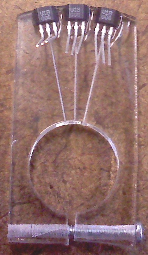
At this point, you need to choose whether you want to go with mounting the hall effect sensors on an internal board 1 2, outside of the motor (usually on some sort of jig / board (scroll down 2/3 page) positioned so that it can pick up the magnetic flux leaking out of the motor), or inside the stator slots 1 2 3 (note: if you mount them on the side of the coils like I did, make sure you make them as close to the magnets as possible) on the coils. The advantage of the former two options is that the board can be rotated to retard or advance the timing of the motor (adjustable timing). The only way to adjust the timing of the third option is in software.
NOTE: It is VERY important to place the hall effect sensors as precisely as possible. Being off by a few mechanical degrees can put you off by many tens of electrical degrees.
If you want to mount the hall sensors on some sort of jig/board (internal or external), then you're done with the math! The above value, m, gives you the number of mechanical degrees that you should space each hall effect sensors apart (for 3 hall effect sensors, that's a total arc of 2*m mdeg). If m is too small for your liking, you can multiply it by any integer value, e.g. 2, 3, 4 etc..., to get other spacings that will work with 120 edeg motor controllers. (While the hall effect sensors will no longer be exactly 120edeg apart, they will be a multiple of 120 edeg apart, which will work, too).
If you want to mount the hall sensors in the stator slots, then you need to find the number of mdeg per slot:
Equation 3: (360 mdeg / s) = x mdeg per slot
Now you need to multiply m from Eq. 2 by integers until you find an integer, i , that gives you a number divisible by x . m*i gives you the number of mdeg you should space the hall effect sensors apart, and:
Equation 4: ((m*i) / x) = # of slots between hall effect sensors.
There are likely multiple choices for i , especially as the number of slots and poles in a motor increases. As long as the above equations are satisfied, then a motor controller that wants the hall effect sensors 120 edeg apart will work. _______________________________________________
Now for motor controllers that requires 60 edeg hall effect sensor placement. Equation 1 still applies, but Equation 2 now becomes:
Equation 2': (360 mdeg / 6*pp) = m mdeg per 60 edeg.
This value, m, gives the minimum number of mdeg that you can space each of the hall effect sensors apart and still achieve 60 edeg spacing. Following the logic from the 120 edeg spacing case above, you can multiply m by any integer and still maintain 60 edeg spacing. You can then directly transfer this number of mdeg to a board/jig for mounting the hall sensors to.
Or you can mount the hall sensors in the stator slots. Doing this is identical to the 120 edeg spacing case; Equations 3 and 4 stay the same for this case.
Note: It is interesting, and logical, that you will obtain all of the 120 edeg spacing multiples in the 60 edeg spacing case (120 is a multiple of 60).
***Note2: You have to be careful with your winding scheme. Winding schemes can affect which mdeg spacings work and which don't. Sometimes you'll have to flip a hall sensor over (see Ex 4 below). For simplicity, you should place the hall effect sensors in sensible locations (first one on or between teeth), despite the fact that it often doesn't matter as long as they're spaced correctly (I say "often" because if the sensors are rotated together, you can adjust the timing of the motor, and thus it's performance and characteristics). *** __________________________________________________
Time for some EXAMPLES!
Ex 1: ELB's motors with internal hall effect sensors mounted on a rotatable "hall board" for 120 edeg controllers.
ELB's motor is a 18 slot, 20 pole brushless outrunner with winding scheme AaABbBCcCAaABbBCcC. At first, I wanted to have the sensors on a hall board that I could rotate about the axle in order to easily adjust the timing. So I did the math: Equation 1: (360 mdeg / 10 pp) = 36 mdeg per erot =n mdeg per 360 edeg Equation 2: (360 mdeg / 30) = 12 mdeg per 120 edeg.
So I spaced the hall effect sensors 12 degrees apart, for a total arc of 24 degrees, which made for a nice, small hall board. (I laser etched the degree lines on the hall boards I cut out, which proved to be super nice for aligning the sensors). This worked. Unfortunately, the little hall boards were very flimsy, and I really didn't have enough room for a hall board inside the motor (or outside), so I went to gluing the sensors into the stator slots...see next example.
Ex 2: ELB's motors with internal hall effect sensors glued into the stator slots for 120 edeg controllers. Time for more math: Equation 3: (360 mdeg / 18) = 20 mdeg per slotEquation 4: ((m*i) / x) = ((12* 5 ) / 20) = 3 slots between hall effect sensors.
So the hall effect sensors needed to be spaced 60 mdeg apart (600 edeg), or one every 3 slots. Which is exactly what I did, and it works great. i = 10 also works, and places the hall sensors 120 mdeg apart, or evenly around the stator. In fact, 120 mdeg works for many common slot/pole combinations...so you could just skip all of this math and do it that way.
I will not be doing a 60 edeg spacing controller in-slot sensors example for the ELB. It turns out that the only mdeg hall spacings that work for 60 edeg controllers with a 18s, 20 pole motor are the same as the 120 edeg spacing mdeg multiples. In other words, the hall sensors end up in the same place as with the 120 edeg spacing case. But don't take my word for it, try the math!
Ex 3: EHB's motors with internal hall effect sensors glued into the stator slots for 120 edeg controllers.
EHB's motors will be 12 slot, 14 pole brushless outrunners with winding scheme AacCBbaACcbB.
Equation 1: (360 mdeg / 7 pp) = 51.4 mdeg per 360 edeg Equation 2: (360 mdeg / 7*3) = 17.14 mdeg per 120 edeg.Equation 3: (360 mdeg / 12) = 30 mdeg per slotEquation 4: ((m*i) / x) = ((17.14* 7 ) / 30) = 4 slots between hall effect sensors. The first multiple i that works is 7. It turns out that the only way to place the sensors in the stator slots when using a motor controller that expects 120 edeg spacing of the sensors, is to place the sensors 120 mdeg apart (spaced equally around the motor).
This is not to say that you couldn't mount the sensors on some sort of jig 17.14 mdeg apart...you can. But if you want the stators in the slots on this type of motor, you have to space them 120 mdeg apart.
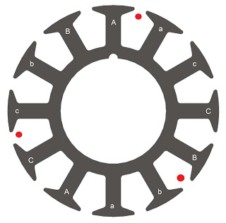
| click me |
|---|
| Red dots indicate slots that the sensors should be placed in. |
Ex 4: EHB's motors with internal hall effect sensors glued into the stator slots for 60 edeg controllers.
Let's take the same motor as in Ex 3, but now the motor controller is expecting 60 edeg hall effect sensor spacing. Equation 1: (360 mdeg / 7 pp) = 51.4 mdeg per 360 edeg Equation 2: (360 mdeg / 6*7) = 8.57 mdeg per 60 edeg.Equation 3: (360 mdeg / 12) = 30 mdeg per slotEquation 4: ((m*i) / x) = ((8.57* 7 ) / 30) = 2 slots between hall effect sensors. Now the hall effect sensors can be placed closer together. However, there is a catch. Since the hall sensors are placed like this: A(sensor)ac(sensor)CB(sensor)baACcbB , the second (C-phase) sensor needs to be flipped over because the magnetic field is reversed in that slot because that slot is wound the other direction compared to the first and third sensors' slots. This is why you have to be careful with winding schemes.
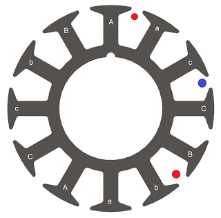
| click me |
|---|
| Blue dot indicates slot where hall sensor should be flipped over. |
________________________________________________
Notes on hooking up the controller to your motor. You will have spend some time testing to see which hall effect sensor corresponds to which phase. And unless you have the ability to modify the code in the motor controller, you will have to play with wire combinations in order to get the correct one. Having a 2 channel scope helps a lot. Since there are many topics on endless-spheres about doing this, and it's dependent on the type of motor you have, I will not go into detail.