Index
- Eclipse IDE and JTAG
- Unlock STM32F103 with JTAG
- Flash firmware using Bluetooth
- Serial Port Bluetooth
- Serial Port Plot
- SM32F103C8T6 use 128kbytes flash
- Observer
- Shane Colton documentation and firmware
- Firmware
- Part 1: Field-Oriented
- Part 2: Field-Oriented
- Sensorless Pneu Scooter - part 1
- Sensorless Pneu Scooter - part 2
- Sensorless Pneu Scooter - part 3
- Texas Instruments videos
- Chinese controllers code
- Chinese balance group reference design
- Kerry D. Wong -- A Self-Balancing Robot
- Self balance bicycle
- PID
- LQR
- PID and LQR, MATLAB
- Steve Brunton videos
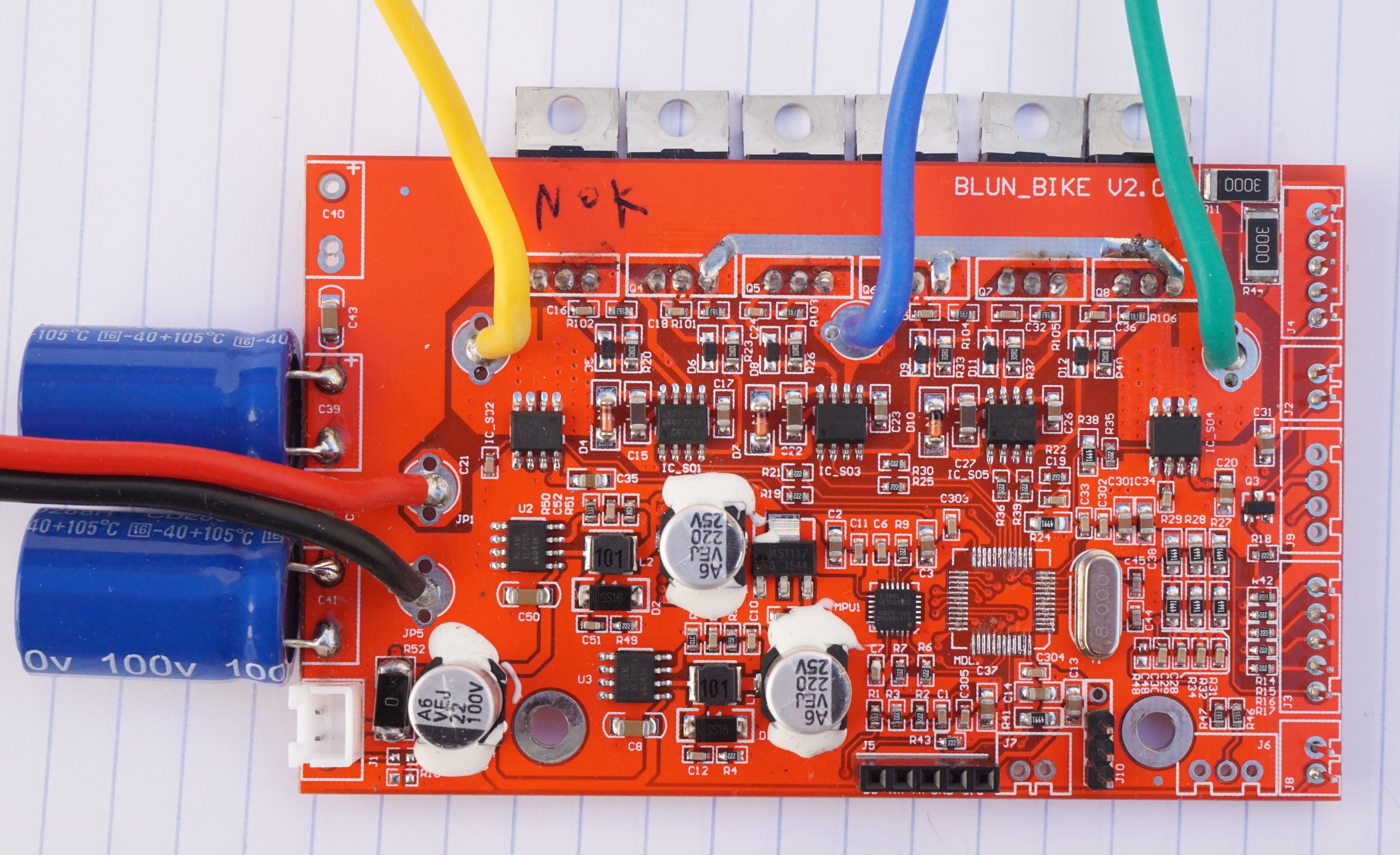
MicroWorks 30B4 board
This 30B4 board from MicroWorks is really "clean" and simple, which makes it very good for repair and hacking. The STM32F103 microcontroller, the USART bluetooth module, the MPU6050 chip for measuring the angle, the ACS712 current sensors, the IR2184s mosfets drivers, all of them are very well know from OpenSource Arduino world!! They are also cheap (which makes also the board cheap!!), easy to find on Ebay and easy to unsolder/repair and there are many documentation, circuit examples.
Also the bluetooth communication data is well known and thanks to that there are a few apps available, including OpenSource ones like the EGG app.
This boards works with MicroWorks 500W 30km/h motor.
Picture of the board (missing some headers plastic parts, the microcontroller and the bluetooth module):
Schematic
• Seller MicroWorks: http://microworks.en.alibaba.com/
• Product page: http://wholesaler.alibaba.com/product-detail/2016-balance-scooter-controller-Motherboard-with_60376493987.html
• Simplified schematic, designed on KiCAD: https://github.com/EGG-electric-unicycle/electronics-gen2_boards/raw/master/MicroWorks_30B4/MicroWorks_30B4.sch.png
• Sources on github: https://github.com/EGG-electric-unicycle/electronics-gen2_boards
Active component list:• 1x ASM1117 3.3v Linear Voltage regulator for 3.3v on Invensense 6050 and STM32
• 2x ACS712ELCTR-05B-T (+-5 amps max) ma Hall Current Sensor on 2 separate Phases - To measure phase current
• 3x IR2184s Gate Driver for Half Bridge. Built in fixed Deadband 1 for each N-Fet Pair
• 2x XL7005A SMPS Max 80v input Output can be adjusted 1 is used to produce 15-20v for Gate driver IC's The other most likely produces 5-12v for Current sensors or maybe just the 1117 to produce 3.3v with minimal losses.
• 1x Invensense MPU6050 (needs no introduction) 6Axis Accel/Gyro with nifity build in filtering
• 1x STM32F103C8T6 ARM microcontroller
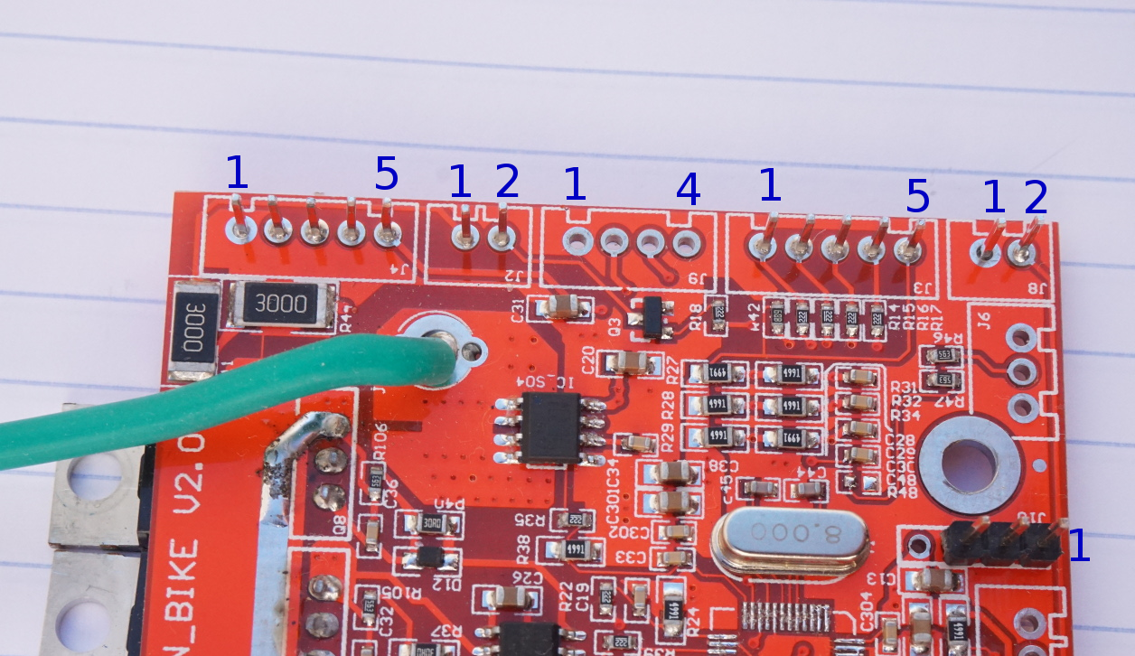
Header pins
The next pictures show the labels according to the previous schematic.
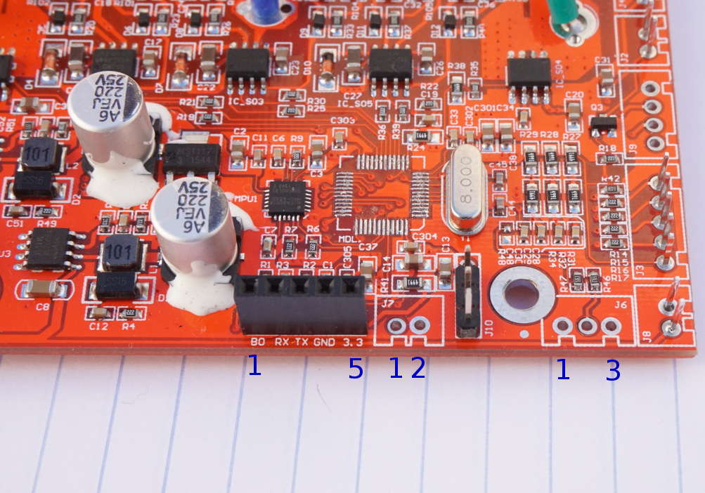
Bluetooth / UART signals
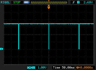
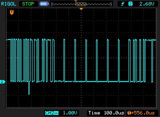
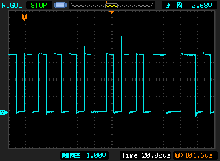
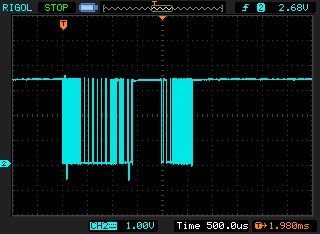
The board is always sending data about the board voltage, motor speed, motor current, etc. The baud rate is 115200 bits/s.
Please see the MOD and Arduino firmware to understand that data that is sent: MicroWorks-30B4-controller-board-RGB-LED-strip
The data is sent every 200ms, as shown on next oscilloscope screenshots:
Max temperature protection
When the temperature achieve 65ºC, the EUC will make 2 quick beeps and tilt back the pedals. Here is a screenshot showing the app and the temperature on that situation:
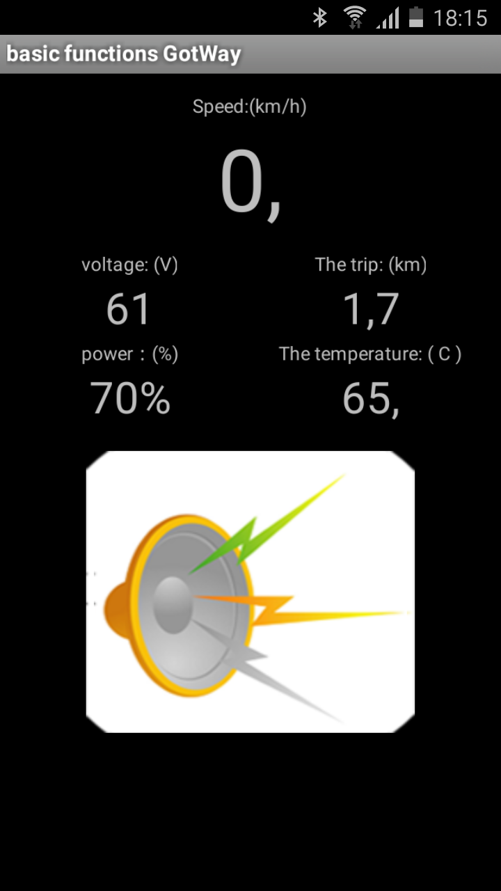
There is no temperature sensor on the board. I believe the system uses the temperature value returned by the MPU6050.
The STM32F103 also have an internal temperature sensor but seems this sensor would need to be calibrated on production line.
UART Bluetooth protocol information
START sequence: 0x18 0x5A 0x5A 0x5A 0x5A 0x55 0xAA
The next following 12 bytes will contain the following data, and calculate the real value:
Voltage = signed 16bit int, real value = value / 100.0 (ie 188C = 6284 / 100 = 62.84V)
Speed = signed 16 bit int, real value = value / 100.0 * 3.6
Trip = signed/unsigned 32 bit int, real value = value / 1000.0 (kilometers)
Current = signed 16 bit in, real value = value / 100.0 (A)
Temperature = signed 16bit int, real value = value / 340.0 + 36.53 (Celsius)
Unknown: 0x0 (this value sometimes is 0, 1 or 2)
END sequence: 0x0 0xff 0xfe 0x0
Commands:
• Beep: Vibrate during five seconds: "b"
• Vibrate during five seconds: ",bbbbbbbbb"
• Ride mode - Madden: "hb"
• Ride mode - Comfort: "fb"
• Ride mode - Comfort: "sb"
• Horizontal alignment: ",cycycy"
• View current: "m"
• Check temperature: "n" - looks like it could be continuously send to the wheel at some point, but I haven't figured out the logic which does it at least yet
NOTE: all the bytes sent in the commands should have a delay of 500ms between each of them.
Thanks to esaj for documenting the protocol: http://forum.electricunicycle.org/topic/870-gotwaykingsong-protocol-reverse-engineering/#comment-9039
Firmware programming over Bluetooth
The STM32 boot0 pin is connected to 3.3V with a pullup resistor, this means that the code that boots at reset time is the firmware. The same boot0 pin connected to the the UART Bluetooth module header, with label "BO" and this means that the module can enable the flash programming by connecting this pin to GND. If the firmware have a command to reset the STM32, it will reset to STM32 bootloader and the firmware can be then programmed by bluetooth. NOTE: Original firmware have Serial Wire Debug (SWD) disabled and so to enable it, just connect the boot0 pin to GND and use SWD to erase the STM and it will then be ready to be flashed and debugged.
Battery voltage and power
When the power available is 20% or less, the board will beep (even when the motor is stopped).
Some of the following values were measured and others were extrapolated.
| click me | click me |
|---|---|
| Voltage (v) | Battery state of charge (%) |
| < 53.0 | 0 |
| 53.0 | 10 |
| 54.1 | 20 |
| 56.2 | 30 |
| 57.7 | 40 |
| 59.1 | 50 |
| 60.5 | 60 |
| 61.7 | 70 |
| 62.8 | 80 |
| 63.9 | 90 |
| 65 | 100 |