Index
- Eclipse IDE and JTAG
- Unlock STM32F103 with JTAG
- Flash firmware using Bluetooth
- Serial Port Bluetooth
- Serial Port Plot
- SM32F103C8T6 use 128kbytes flash
- Observer
- Shane Colton documentation and firmware
- Firmware
- Part 1: Field-Oriented
- Part 2: Field-Oriented
- Sensorless Pneu Scooter - part 1
- Sensorless Pneu Scooter - part 2
- Sensorless Pneu Scooter - part 3
- Texas Instruments videos
- Chinese controllers code
- Chinese balance group reference design
- Kerry D. Wong -- A Self-Balancing Robot
- Self balance bicycle
- PID
- LQR
- PID and LQR, MATLAB
- Steve Brunton videos
ZS-040 Bluetooth module
http://www.martyncurrey.com/hc-05-and-hc-06-zs-040-bluetooth-modules-first-look/HC-05 and HC-06 zs-040 Bluetooth modules. First Look
Posted on October 4, 2014 Update: If you have modules that have a blue LED in the top left hand corner then you have a newer model with a slightly different firmware although they should operate the same.
I recently bought some HC05s and HC-06 Bluetooth modules. These are pretty standard, especially when using with the Arduino and I was surprised at how easy it was to get basic serial communication working. There are several slightly different modules available. The ones I have are marked zs-040. The zs-040 boards differ from some of the other modules in that they have a EN pin rather than a KEY pin.
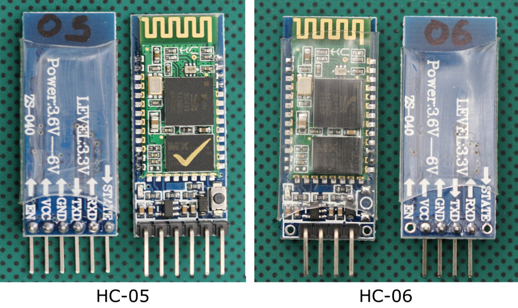
The HC-05 zs-040 and the HC-06 zs-040 use the the same breakout board (even have the same screen print) but have some noticeable differences:
– the HC-06 does not have a button switch
– the HC-06 only 4 header pins
– the HC-06 does not have pins 31-34 connected
They also have a different firmwares. The HC-05 can be a master or slave. The HC-06 is a slave only. This means the HC-05 can initiate a connection to another device and the HC-06 can only accept a connection from another device.
The boards are based on the EGBT-045MS/EGBT-046S Bluetooth modules which are loaded with SPP firmware for UART communication.
Specifications of the EGBT-045MS/EGBT-046S Bluetooth modules
Radio Chip: CSR BC417
Memory: External 8Mbit Flash
Output Power: -4 to +6dbm Class 2
Sensitivity: -80dbm Typical
Bit Rate: EDR, up to 3Mbps
Interface: UART
Antenna: Built-in
Dimension: 27W x 13H mm
Voltage: 3.1 to 4.2VDC
Current: 40mA max
As far as I can tell the EGBT-045MS and EGBT-046S modules have the same hardware and the only difference is the firmware. The different firmware does change the pin outs though.

The zs-040 breakout boards include a 3.3v voltage regulator and this allows the boards to accept a VCC of 3.6c to 6v on the main VCC pin/connector. However, the RX and TX pins are still 3.3v.
The Arduino will accept 3.3v as a HIGH signal so the HC-05/06 TX pin (out) can be directly connected to a 5V Arduino. The HC-05/06 RX pin (in) cannot accept 5V though and should not be connected directly to an Arduino. A direct connection will work short term but it damages the small blue tooth module and eventually you will kill the RX pin. The 5V rom the Arduino has to be reduced in some way and a simple way to do this is by using a voltage divider made from 2 resistors. I generally use a 1K ohm resistor and a 2k ohm resistor.
Breakout Board Connections
The below image shows the main traces/connections on the zs-040 breakout board and as you can see, to accomodate the different firmwares certain pins have been connected together.
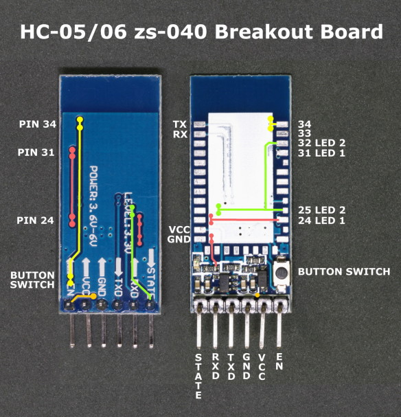
The HC-06 does not have the EN pin or the STATE pin.
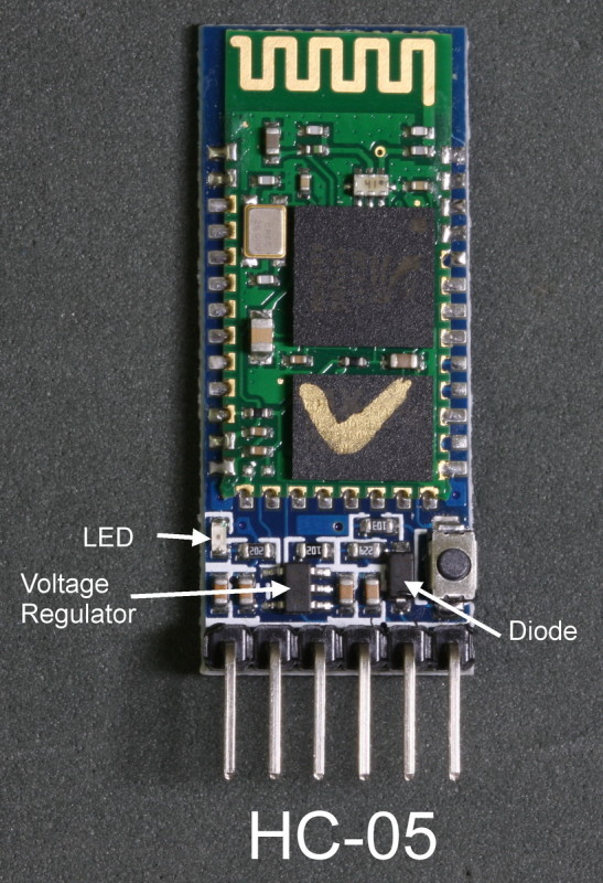
LED
The trace between pin 31 and pin 24 on the breakout board links the status LED pin on the EGBT-045MS to the status LED pin on the EGBT-046S. The connection then goes to the actual LED on the breakout board. The connection between pin 31 and pin 24 allows the same breakout board to be used for both the EGBT-045MS and the EGBT-046S
Button Switch
The push button switch connects VCC (3.3v) to pin 34 and is used to put the EGBT-045MS / HC-05 in to AT mode. There are 2 AT modes, I refer to them as “mini mode” and “full mode”. Briefly pressing the button switch puts the modules in to mini mode and not all commands work. Keeping the switch closed puts the modules in to full AT mode where all AT commands work. Releasing the switch returns pin 34 LOW.
For more on AT commands see Arduino with HC-05 (ZS-040) Bluetooth module – AT MODE
Most HC-06 modules do not have the button switch (the space is empty) and bringing pin 34 HIGH on the HC-06 does not do anything.
STATE Pin
From the above photo you can see that the STATE pin is connected to pin 32 and to pin 25 of the small blue tooth modules. Pin 32 is LED2 on the EGBT-045MS/HC-05. Pin 32 is LOW when the module is not connected and HIGH when the module is connected. This gives us an easy way to determine if the HC-05 is actually connected or not. Connect the STATE pin to an Arduino digital pin and if digitalRead() returns HIGH you know the module has an active connection. You can, of course, connect an LED to the STATE pin as a visual indicator of a connection.
I haven’t tried this on a HC-06 yet but since this is not mentioned in the manual I believe it is not active.
EN Pin
Pulling the EN pin on the HC-05 LOW disables the module.
Datasheet
| Linked file: HC-06 english datasheet.pdf |
Hardware Manual & AT Commands Reference Manual Rev. 1r0:
| Linked file: EGBT-045MS & EGBT-046S Hardware Manual & AT Commands Reference Manual Rev. 1r0.pdf |