Index
- Eclipse IDE and JTAG
- Unlock STM32F103 with JTAG
- Flash firmware using Bluetooth
- Serial Port Bluetooth
- Serial Port Plot
- SM32F103C8T6 use 128kbytes flash
- Observer
- Shane Colton documentation and firmware
- Firmware
- Part 1: Field-Oriented
- Part 2: Field-Oriented
- Sensorless Pneu Scooter - part 1
- Sensorless Pneu Scooter - part 2
- Sensorless Pneu Scooter - part 3
- Texas Instruments videos
- Chinese controllers code
- Chinese balance group reference design
- Kerry D. Wong -- A Self-Balancing Robot
- Self balance bicycle
- PID
- LQR
- PID and LQR, MATLAB
- Steve Brunton videos
Finding Motor Phase-Sensor Combinations
http://e0designs.com/documentation/finding-motor-phase-sensor-combinations/
Finding Motor Phase-Sensor Combinations
If you have a motor that you do not know the internal winding scheme of, you will need to find empirically one of two motor states:
• The combination of Hall sensor signals for a given phase connection (“sensor combo”) that yields commutation, for a given controller, or
• The combination of phase wire connections for a given Hall sensor connection (“phase combo”) that yields commutation, for a given controller
This exercise is practically required when all 3 components – motor, sensors, and controller – are purchased separately. Chances are, connecting any random combination of Halls and phases will not result in motion. Mathematically, there are 12 unique possible combinations of 3 Hall sensor signals and 3 phase connections, and only 2 of them result in commutation – one in each direction (the others are rotationally symmetrical).
This document presents a relatively simple heuristic to find the phase combination for a given Hall sensor connection. The reason is the phase connections are generally made easier to connect and access than the much smaller sensor cable, which may be embedded in a connector with other signals, making them more difficult to arrange.
There are three major steps to the process after a Hall sensor:
• For a given starting configuration of phase connections, swap 2 at a time until all 6 unique combinations have been tried; one will result in motor commutation.
• If the commutation is opposite the desired direction, cyclically shifting all 3 phase connections up to 2 times to reverse the motor commutation direction.
• Timing the sensor by slightly shifting the position of the sensor board to achieve optimal commutation at a given speed, for that direction only.
Summary of Procedure
In more detail, the general procedure is:
1. Begin with the motor connected with a known Hall sensor combination and labeled phase connections (e.g. UVW on controller, ABC on motor, connected UA, VB, WC), and one sensor aligned with the middle of a slot (gap between 2 stator teeth)
2. Attempt to run the motor.
3. If no continuous commutation is observed, perform the following steps:1. Swap two phase wires, keeping one unique from the previous swap (if it is the first swap, pick any two). Keep track of which ones you swapped!
2. Attempt to run the motor.
3. If no continuous commutation is observed, return to Step A. There are six possible combinations to try:• UA, VB, WC
• UA, VC, WB
• UB, VC, WA
• UC, VB, WA
• UC, VA, WB
• UB, VA, WC
• If still no rotation is observed, swap 2 Hall sensor signals and return to Step 2.
• If rotation is observed and is the correct direction, go to step 7.
• If rotation is observed and is the opposite direction, cyclically shift all phase wires and attempt to run the motor (e.g. UA,VB,WC becomes UC,VA,WB). At least one cyclic shift within 2 attempts will be the reverse direction (The 3rd shift, of course, will result in the original combination!)
• Using an ammeter to read the phase current (AC ammeter) or Battery side current (DC ammeter), slightly shift the sensor board in either direction in its mounting slots to find the region of lowest current draw for a given motor speed. This is the point of optimal timing for that speed. The speed you select should be dependent on the need for low end start-up stability vs. high speed efficient operation.
Caveats
This procedure demonstrates how to find the sensor position for one direction. By optimizing the timing for one direction, the timing in the reverse direction could be very poor, resulting in higher current draw and lower torque. For most traction applications, limited reverse speed and torque is acceptable.
The digital latch type Hall Effect Sensor Boards are not recommended if symmetric, bidirectional operation is desired, for instance in high precision robotic actuators or drivetrains.
While an “untimed” sensor board will allow for bidirectional operation, the efficiency at higher speeds and loads will be negatively affected compared to a well-timed sensor: the motor will draw more current, spin at a lower speed, and produce less torque per ampere. Use these instructions at your own risk!
More Details: Motor Combo Finding
The following is a picture walkthrough of an example motor with more indepth explanation.
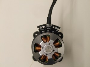 Begin by aligning one sensor of your choice with the exact center of a slot (gap between 2 teeth). This guarantees that this sensor will switch states approximately when two magnets are almost exactly aligned with two stator teeth, a position where the motor will generate no torque (hence a need to switch the coils at that point).
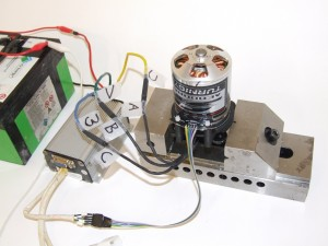
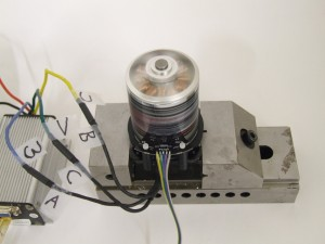
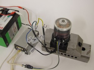
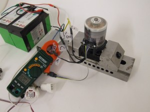
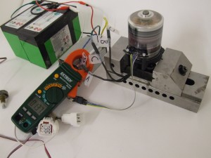
The test setup is a Kelly KBS36051 sensor-commutated controller and a Turnigy SK3-6364 motor with 59mm Hall Effect Sensor Board, running on 24 volts. The sensor arrangement is fixed with Hall signals A, B, and C on the Kelly being connected to signals A, B, C on the board (arbitrarily selected for easy wiring). The phase connections have been labeled, arbitrarily, UVW on the Kelly and ABC on the motor, with UA,VB,WC being the starting configuration.
A small amount of throttle command was given to make the motor rotate. No rotation was observed; the motor stalled after moving a few degrees. The combination UA,VB,WC is invalid.
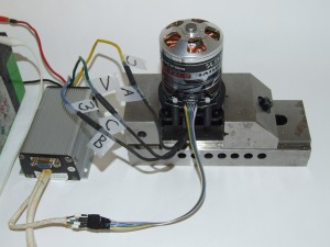
Swap 2 phase wires. In this case, I have switched B and C on the motor. The combination is now UA,VC,WB.
This combination also resulted in no motion. The motor vibrates back and forth. Swap 2 phase wires, keeping one from the previous step constant. The new combination is now UB,VC,WA.
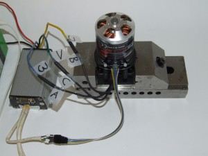
Continue testing the motor for commutation, repeating the above procedure as needed. A full set of “phase combos” for this sensor arrangement would go:
• UA, VB, WC
• UA, VC, WB
• UB, VC, WA
• UC, VB, WA
• UC, VA, WB
• UB, VA, WC
If none of the above result in motor commutation, there are two options:
• Move the sensor board such that a different sensor is lined up in the center of a different slot
• Swap two Hall sensor leads (e.g. switch Hall A and Hall B)
Afterwards, repeat the combination of phase leads.
In this example, the combination UB,VC,WA resulted in the motor rotating counterclockwise as viewed from above. The characteristics of a valid combination are smooth running, no cogging (shaking) during starting, and torque at low speed.
If the motor is spinning opposite the desired direction, cyclically shift all three phases. The connection in this example becomes UC, VA, WB.
You may have to do this twice in order to effect a rotation change – one of the three cyclic combinations is invalid.
More Details: Motor Timing
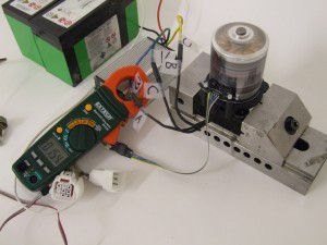
The next step is finding the optimal sensor timing. This requires an AC or DC ammeter. If an AC ammeter is used, it must be sensing a phase wire. If a DC ammeter is used, it must be sensing the battery input of the controller.
Begin by spinning the motor up to about 50% speed. Note that this procedure sets optimal sensor timing for that speed only. Timing at higher speeds will be retarded (triggering too late) and timing at lower speeds will be advanced (triggering too early). This is a consequence of simple “block” or square wave commutation employed by almost all BLDC controllers, and there is no workaround within the scope of this document.
Be aware that timing the sensors at too high of a motor speed can result in unreliable starting behavior, as the sensors are too advanced and trigger early enough to push the motor “back”; conversely, timing the sensors at too low of a motor speed results in excessive current draw at high speeds, as the late trigger causes the current in the windings to pull the motor back. 50% is a compromise speed and you may change it at will to suit your needs.
The initial current draw in this example is 1.54 AC amperes, +/- approximately 0.05 in fluctuations displayed on the ammeter.
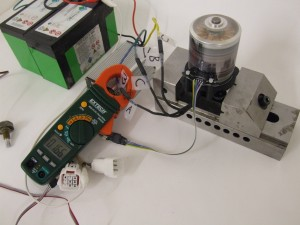
Moving the sensor board against the motor rotation causes an increase in current draw because the sensors are triggering on earlier and earlier magnet positions (advancing timing). The motor speed will noticeably increase during this time.
Conversely, the sensor board being moved in the direction of the motor rotation results in retarded timing. Current draw also increases because the motor winding current is pulling the magnets back. The motor will noticeably decrease in speed during this time.
Move the hall sensor board very slightly in either direction to find the point of minimum current draw. This is the optimal timing position for this motor, at the given speed. The measurement will not be perfect – don’t spend an hour adjusting out 0.01 amps! Generally, being within 5% higher or lower than the lowest observed reading is close enough. In this case, the observed minimum was approximately 1.37 amps fluctuating up to 1.45.
After this is done, congratulations! You’ve found the phase combination for your motor setup and the optimal sensor timing location. Write this down, mark it, label your wires, do something so you can remember it! Tighten down the sensor board mounting screws fully to prevent them from vibrating loose and the timing changing uncontrollably. The sensor boards come with 120 electrical degrees of adjustment for maximum mounting flexibility – moving them to either extreme is tantamount to changing two wires on your phase combinations, so you must keep the board from shifting.