Index
- Eclipse IDE and JTAG
- Unlock STM32F103 with JTAG
- Flash firmware using Bluetooth
- Serial Port Bluetooth
- Serial Port Plot
- SM32F103C8T6 use 128kbytes flash
- Observer
- Shane Colton documentation and firmware
- Firmware
- Part 1: Field-Oriented
- Part 2: Field-Oriented
- Sensorless Pneu Scooter - part 1
- Sensorless Pneu Scooter - part 2
- Sensorless Pneu Scooter - part 3
- Texas Instruments videos
- Chinese controllers code
- Chinese balance group reference design
- Kerry D. Wong -- A Self-Balancing Robot
- Self balance bicycle
- PID
- LQR
- PID and LQR, MATLAB
- Steve Brunton videos
Sensorless Pneu Scooter - part 3
Friday, December 23, 2011
More Sensorless
I'm still tweaking the sensorless routine for
Pneu Scooter. The software framework for sensorless sinusoidal commutation and field-oriented current control is set, and now I am playing with the different parameters to see if they have the effects I think they should.
First, I hypothesized in the
last postthat the positive relationship between current and flux estimator offset (with respect to the Hall effect sensors), seen
here
, was due to underestimated inductance. At high current, the rotor electrical angle predicted by the flux estimator would lead the angle interpolated from the Hall effect sensors, which I trust to be more accurate. Based on
this figure
, if the inductance parameter is too low, the [-IL] vector will be too short and the estimated flux vector will lead the actual flux vector at high current.
To test this, I changed only the
L
parameter in the sensorless code definitions, from 200μH to 300μH, leaving all other settings the same. After another 15-minute outdoor test drive, I plotted the flux estimator offset as a function of current once again. Here it is with the old data for comparison:
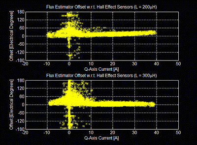
The effect is exactly what I thought it would be, flattening out the slope so that the offset is constant (near zero) though the entire range of load currents. I may have even gone a bit too far, creating a very slightly negative slope. But now I know that the inductance parameter has as predictable effect. The lead induced by using an inductance parameter that was 33% too low was about 20º electrical at maximum current. The error sensitivity is easy to predict using the vectors in this figure, but I will spare you the analysis in this post.
A closed-loop flux observer, which some day in the future I will certainly try out, would seek to minimize the effect of an over- or under-estimated inductance parameter. The ultimate goal would be plug-and-play sensorless that adapts to any motor on the fly. But for now, I can live with nicely-behaved dependencies like this. Though, without the parallel-processed Hall effect sensor data, I would be lost as to how to characterize any of it.
I also tried out the sensorless controller on a different motor:
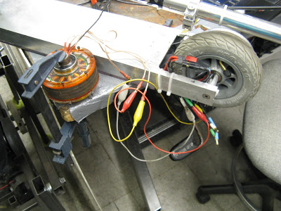
The thing clamped to the table is Kitmotter, a demonstration motor with very similar characteristics to Pneu Scooter's wheel motor. They have virtually the same measured inductance. Kitmotter has a higher resistance, which I modified in the sensorless code definitions for this test. It also has a lower torque constant, which is not an explicit parameter in this sensorless algorithm. What it does mean, though, is that the flux magnitude should be lower:
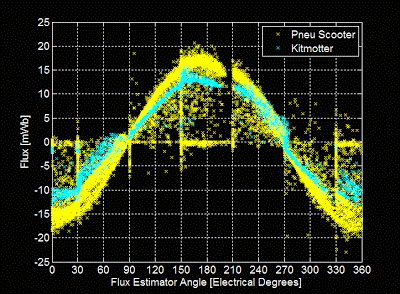
And in fact it is, by a small amount. It's also interesting to see that the general form of the flux estimates is very similar for both motors. In particular, the gap between about 200º and 210º shows up in both cases. This eliminates the possibility that the gap is caused by some asymmetry in one motor's winding. It could be current sensor asymmetry, though.
Kitmotter also accidentally allowed me to test the fast overcurrent shutdown. The dangling mess of alligator clips seen above was not the best idea, and when two of the phase outputs shorted to each other, causing a large spark, the controller shut down properly and gave an overcurrent fault. No dead FET.
The next parameter I want to tweak is the low-pass filter time constant, which affects the low speed performance of the sensorless control. I mentioned that the low-pass filter causes the flux estimator to lead the true angle at low speeds, and showed the offset as a function of speed. Here it is again, but in pseudo-3D:
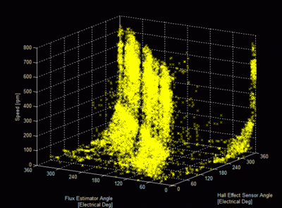
| click me |
|---|
| Is this nauseating? |
Below 200rpm, the flux estimator angle is greater than the Hall effect sensor angle (trusted to be the true electrical angle). This causes the data, which should lie on the x = y plane, to slope off to the left at low speeds. Making the low-pass filter time constant longer should flatten out the plane and improve the low-speed torque. A lower "valid data" speed for switching to sensorless control will make start-up ramping, when I get around to that, just a bit easier.
I'm also worried about high-speed operation, which was the problem that magically disappeared when I made several code improvements. But, I'm still working with relatively slow motors, having commutation frequencies of 200Hz or less. I'm interested to see how things change (probably for the worse) when I try to run a non-direct-drive (indirect-drive?) motor like that of tinyKart, which can hit 750Hz or more.
More testing to come... Posted by Shane Colton at 7:05 PM Labels: FOC, motor control, pneu, pneu scooter, sensorless