Index
- Eclipse IDE and JTAG
- Unlock STM32F103 with JTAG
- Flash firmware using Bluetooth
- Serial Port Bluetooth
- Serial Port Plot
- SM32F103C8T6 use 128kbytes flash
- Observer
- Shane Colton documentation and firmware
- Firmware
- Part 1: Field-Oriented
- Part 2: Field-Oriented
- Sensorless Pneu Scooter - part 1
- Sensorless Pneu Scooter - part 2
- Sensorless Pneu Scooter - part 3
- Texas Instruments videos
- Chinese controllers code
- Chinese balance group reference design
- Kerry D. Wong -- A Self-Balancing Robot
- Self balance bicycle
- PID
- LQR
- PID and LQR, MATLAB
- Steve Brunton videos
Why does the Torquemax rotate so slowly and so forcefully
https://www.aerodesign.de/peter/2001/LRK350/Warum_dreht_er_so_eng.htmlWhy does the Torquemax rotate so slowly and so forcefully
by Peter Rother
• Classic 3-phase drive
• Torque at 3-phase 2-pole inner runner
• Torque at 3-phase 14-pole outside runner
• Revolution at 3-phase 14-pole outside runner
• Equations for other magnets count
• Animation of rotating 14-pole outside runner
• Measurements on LRK350-20-15
• back to LRK main site
This question was amazing me months ago. Therefore I've started to seek answer. After reading the first article by Ludwig Retzbach in German Electro-Modell I was not sure, how the rotating magnetic field really works. Why was the opposite winding 180 degree out of phase? After the second article I was little bit clever. But first building the LRK350-20-15 engine and watching it running gave me the whole knowledge. Specially after been exposed to its very strong propeller thrust, I said I had to know why !!!
Classic 3-phase drive
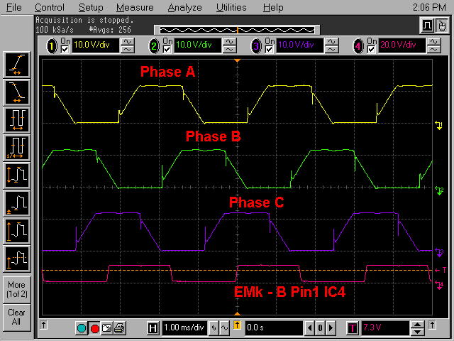
At first we should grab out some knowledge, that many of us have had at school. How does the 3-phase motor work? Let's take a short view on voltages supplied to such 3-phase motor. Each output of such 3-phase driver switch on the negative battery voltage for the whole 120 degrees (see yellow upper trace, marked Phase A) . Than switches off for 60 degrees (line ramps up slowly) and switches on, this time positive battery voltage for 120 degrees. On the end switches off again for 60 degrees. All three controller outputs are shifted by 120 degrees giving totally 6 different drive phases over the whole 360 degrees period (every 60 degrees something happens).
Following diagram has been made during real measurements on brush less controller. Modern digital scopes allow to capture pictures and send them to the PC for further work. The lowest trace (magenta) shows the position signal generated by special circuitry observing voltages on the motor. This signal, one of three, is essential for the microprocessor to determine where the rotator actually resides.
Please click on the diagram to zoom in.

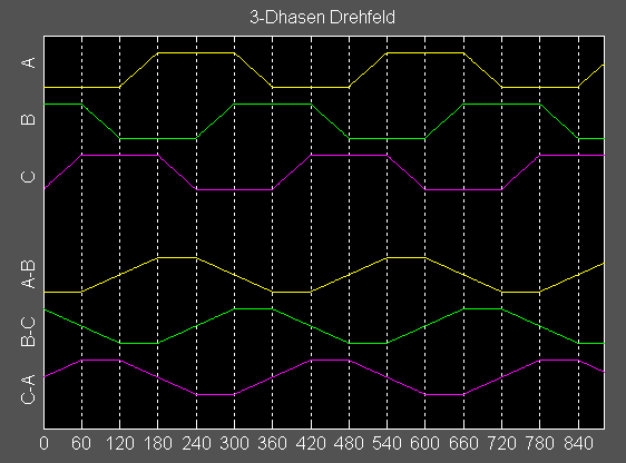
Next picture can not be easy generated on the scope. This picture has been made in MATLAB as subtraction of all Phases, A, B, C. This picture shows currents in our triangle-connected windings. Phase-A to Phase-B is A-B, B to C is B-C and C to A is C-A. We see that currents are very similar to periodic sinus signal, which would be the optimum. These lower-half traces can represent currents, but also magnetic forces in each of 120-degrees-spaced directions. Adding all these vectorial forces give us well known 3-phase rotating field. The magnets, outside or inside, will follow this rotation. This is the principle of every motor.

Torque at 3-phase 2-pole inner runner
The principle showed above will be used in any 2-pole inner runner. Inner runner means: coils are sitting outside in the stator (that stays in place, as the name says) and one magnet with, of course, two poles rotates inside. All modern well known brush less engines follow this principle: AVEOX, Hacker, LMT etc. Diameter of the magnet is small, 10 to 20 mm (1/2 to 1 inch).
While the radius is small, the circumference 2*PI*r is small. Therefore cylinder area is small also. While the Neodym magnets have limited field density, all magnetic forces are small.
Short calculation for 200 watt inner runner:
Magnetic induction in in the magnetic gap between air winded coils and magnets is smaller then 1 Tesla, about 0.8 T. Therefore force per cm^2
F = A x 4 B ^ 2 = A * 2,56 N
Only 65% of the circumference will be loaded with magnets, therefore force per area is:
0,65 x 2,56 N/cm2 = 1,66 N/cm2
In the inner runner with 18 mm magnet diameter and 20 mm magnet length the area is:
A = PI*D*h = 11,3 cm2
Force in the air gap:
F x A = 18,8 N
Torque of magnet with 9 mm radius:
M = F x r = 18,8 N x 0,009 m = 0,17 Nm
Power at 50,000 rpm:
P = 2 * PI * M * rpm /60 = 886 W
Assumed a prop 14x8 with n100w=4240 should be driven by this motor. Such prop rotates with 8773 rpm at 886 W. We have to reduce revolution from 50,000 to 8,773 by gear box of 5.7:1. Torque increases with this ratio to 5.7*0.17=0.97 Nm
Torque at 14-pole outside runner, LRK350-20
Force between stator and magnet cylinder is:
F = A x 4 B ^ 2
For the Neodym magnet with B = 1 T the force per area is 4 N/cm2. Only 65% of circumference will be loaded with magnets. Therefore:
0,65 x 4 N/cm2 = 2,6 N/cm2
At outside runner with 35 mm diameter and 20 mm magnet length the bell area is:
A = PI*D*h = 22 cm2
The force in air gap is:
F x A = 57 N
The torque of this motor is:
M = F x D/2 = 57 N x 0,035 m /2 = 1 Nm
This torque is 6 times higher, than for the presented inner runner. At this moment we see that
LRK350-20 doesn't need any gear box and can drive big props directly.
Number of revolution at Torquemax

Time point Phase A
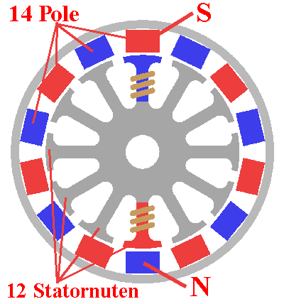
In this picture current flows through upper coil (Phase A in 3-phase system) and the S-pole magnet will be pulled. This is a stable position. No magnet will pulled to the left or right.
Phase A/B - 60° to the right.
In this 12-slot stator only evehttps://www.aerodesign.de/peter/2001/LRK350/Warum_dreht_er_so_eng.htmlry second tooth will winded. Now, 60 degrees to the right, current flows through the coil on the 3rd tooth (not show on the picture). The magnetic field has rotated also 60 degrees to the right. There are 14 magnets in the bell, 7 pole pairs over 360 degrees distributed. Look at the picture. When 3rd tooth is energized, the next S-pole (red one in the picture) is in the position of 360/7=51.42°. This pole will pulled to the right by the angle of
Delta phi = 360/6 - 360/7 = 360/42 = 8.57°
This is the point! The field has rotated by 360/6=60° and the magnets bell only by 360/42=8.57°, 7 times slower.
When the field rotates 360° during the whole one 3-phase cycle, the magnets bell rotates only by 360/7=51,43°.
When the field rotates 360° during the whole one 3-phase cycle, the magnets bell rotates only by 360/7=51,43°.
Now little bit mathematics:
The LRK motor is a special motor (only second tooth winded). The number of magnetic pole pairs must be greater or smaller by one then number of stator winded teeth. In our case 6 winded teeth and 7 magnet pairs.
Equations:
k=1,2,3,4,... at LRK k=1
winded teeth/slots = 6 * k = 6
Stator-slots = 12 * k = 12
Magnets-pole-pairs = 6 * k +/- 1 = 7
Magnets count = 2 * 7 = 14
revolution reduction = 1 / pole pairs = 1 / 7
Animation of the rotating 14-pole outside runner.
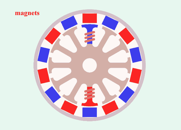
I have made this animation to show how it works. Look at one red magnet for few seconds and then at rotating coil, that represents rotating magnetic field. The magnetic bell is rotating 7 times slower.

Praxis:
The 3-phase field is rotating at 42,000 rpm, the magnets bell and he propeller at 42,000/7=6,000rpm.
Many measuremnst are done here
Summary:
1. The torque for outside runner is much higher then for inner runner, practically 4 to 8 times higher.
2. Because of the ratio 7 to 6, the propeller is rotating 7 times slower, then magnetic field.